Background
Amongst my far too many hobbies, I am an amateur photographer. (In fact, my minor is in art / visual design, most of which was photography.)
While I shoot a lot of digital photography (mostly with whatever phone is in my pocket, sometimes with a sony mirrorless ILC), I’ve recently revived my interest in film photography.
I carry an Olympus XA with me almost everywhere, loaded with black and white film.
Black and white film is a little hipster, but it’s easy to work with from a chemistry perspective- I process my own film, at home, with the help of a changing bag and light tight processing tanks (mine are from Jobo but other systems exist.)
What I don’t have at home is a true darkroom, an enlarger, or the capacity to make prints from my negatives.
What I do have is a dedicated film scanner, an Plustek OpticFilm 7400 that I bought used off of eBay.
The Plustek OpticFilm 7400
The scanner works well, despite its age- scanners work in such closely controlled environments that their technology has not significantly improved in the last 30 years. Mostly they just get smaller and/or faster. Some higher end film scanners include IR light sources that can let them automatically detect dust on negatives, though the Plustek OpticFilm 7400 does not.
Unfortunately, the Plustek OpticFilm 7400 only ships with drivers for Windows and macOS.
Fortunately, the venerable SANE Project has a driver for the main IC that powers the Plustek OpticFilm, a chip from Genesys Logic known as the GL843.
The SANE genesys Driver
Unfortunately, the SANE drivers for my Plustek OpticFilm 7400 did not fully work. It turns out that Plustek made a few variants of the OpticFilm 7400 without rebranding them in any way, and mine is the earlier revision; the SANE drivers (presumably) work for the later revision.
Attempting to scan a negative in greyscale mode produces a corrupt image:

Scanning in color worked well (though I found and fixed a bug effecting all JPEG output from 16-bit sources in SANE), but this meant sacrificing quality and speed by scanning in color and needing to convert to greyscale in software.
The OpticFilm / Genesys GL843 Architecture
The GL843 is the brain of the scanner. It communicates with the attached computer via USB, controls motor movement, the scanner’s lamp, controls the CCD or CIS , and reads data out from a separate ADC .
The GL843 is a pretty generic chip, and it doesn’t know much about the hardware it’s connected to. The driver, running on the attached computer, sends over all of the relevant configuration data.
Somewhere in this data (or the instructions sent to initiate a scan), the open source driver is sending the wrong information.
Finding the Right Information
I took two approaches to finding out how to configure the GL843 to work with my scanner:
- Reading the datasheet, which I was able to find from third-party sources; and
- Analyzing traffic sent from the windows drivers to the scanner during a scan operation.
Getting packet dumps of the USB traffic was pretty easy- the driver works well in a virtualized environment (VirtualBox via Vagrant), and VirtualBox allows me to direct USB traffic out to a file:
# find a VM UUID
$ VBoxManage list vms

# find the USB device UUID
$ VBoxManage list usbhost

# attach the USB device to the VM and capture traffic
$ VBoxManage controlvm <vm-UUID> usbattach <usb-device-UUID> --capturefile=path/to/packet.pcapng
Understanding the contents of this was more complicated. Here, I relied on reading the datasheet – most USB operations are modifying GL843 control registers, or issuing commands by writing to control registers. I’m familiar with this, conceptually, because I’ve done a lot of low-level work with AVRs (the Atmel microcontrollers that power most Arduinos.)
Some of the GL843 registers are effectively pass-throughs to the attached ADC. This is a little more difficult to understand, because I don’t know what ADC is attached to the GL843, which supports multiples.
I was also able to gain more understanding by reading the source code of the existing SANE driver. The driver mostly works, there are just some parameters that are wrong.
This work culminated in a (mostly complete) wireshark dissector that can analyze gl843 USB traffic. You can grab the source code, if you want it.
Get a copy of the wireshark source tree, drop packet-gl843.c into the
epan/dissectors/ directory, add the dissector to CMakeLists.txt:
$ git diff dissectors/CMakeLists.txt
diff --git a/epan/dissectors/CMakeLists.txt b/epan/dissectors/CMakeLists.txt
index a7fc50c..8c5f083 100644
--- a/epan/dissectors/CMakeLists.txt
+++ b/epan/dissectors/CMakeLists.txt
@@ -1198,6 +1198,7 @@ set(DISSECTOR_SRC
        ${CMAKE_CURRENT_SOURCE_DIR}/packet-gift.c
        ${CMAKE_CURRENT_SOURCE_DIR}/packet-giop.c
        ${CMAKE_CURRENT_SOURCE_DIR}/packet-git.c
+       ${CMAKE_CURRENT_SOURCE_DIR}/packet-gl843.c
        ${CMAKE_CURRENT_SOURCE_DIR}/packet-glbp.c
        ${CMAKE_CURRENT_SOURCE_DIR}/packet-gluster_cli.c
        ${CMAKE_CURRENT_SOURCE_DIR}/packet-gluster_pmap.c
…then compile (and optionally install) wireshark according to the documentation. The dissector hardcodes the USB device ID that it targets, at the very end of the file. If you’re trying to analyze a difference scanner, you’ll need to update the vendor and product ID.
Once you have a packet trace loaded up and the dissector compiled in, you can
filter packets for gl843, to find relevant traffic, and examine packets.
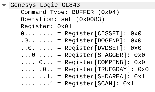
Here’s an example breakdown of the command from the driver to the scanner to
trigger a scan (SCAN register set to 1).
Making Changes
I wish this part was more scientific. There’s a lot I don’t understand about the image processing flow. The GL843 datasheet is fairly complete as far as descriptions of registers, but there are a few challenges:
It assumes a lot of knowledge of image processing hardware; or perhaps assumes you’re working with an engineer from Genesys.
Some commands are passed through to the ADC, and the documentation only documents how to forward a command, not what any of those commands do
Both drivers contain a lot of what is probably cargo-culting – setting registers to various values for no very obvious reason
Working on the fix involved a lot of trial and error, and hypothesis testing.
“Maybe the problem is that the AFE
mode is
wrong…” so wire AFEMOD into the dissector, see what the proprietary driver
sets, and then dig around in the SANE source code and try changing it - but
nothing happens.
Some of this hypothesis testing resulting in code cleanup/tidying in the open source driver, which made its way into the final PR.
While working on this, I discovered a feature in the chipset called LPERIOD:
Line period (or exposure time) for CCD or CIS., and
added support
to SANE for it. Cool.
Ultimately, my pull request captured three main changes from the “7400 v2” settings:
- Re-mapping
DPISETvalues to scan resolutions – this was the primary fix, yielding much more usable images - Disabling built-in shading – shading calibration was producing striping / tone variation on the images; if I understood more about shading (see my comments above regarding the documentation challenges), this would probably be fixable
- Adjusting scan dimensions – the “noise” bar at the side of the image is part of the scanner’s calibration zone, which should not be included in the scan, and the original scan dimensions also cropped out potentially usable sections of the scan area
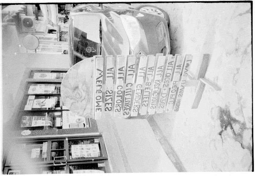
Here’s the final result- this is the same negative frame that was completely corrupt before:
A Word of Caution
These types of changes can be dangerous; the OpticFilm 7400, at least, does not have a lot of hardware failsafes for the motors, and running them into their mechanical limits could cause damage to the hardware. I had some head crashes- but luckily nothing broke.